A Digital Readout Caustic Tester
An Accurate Multi-Purpose Tester
By T. LumFebruary 15, 2001

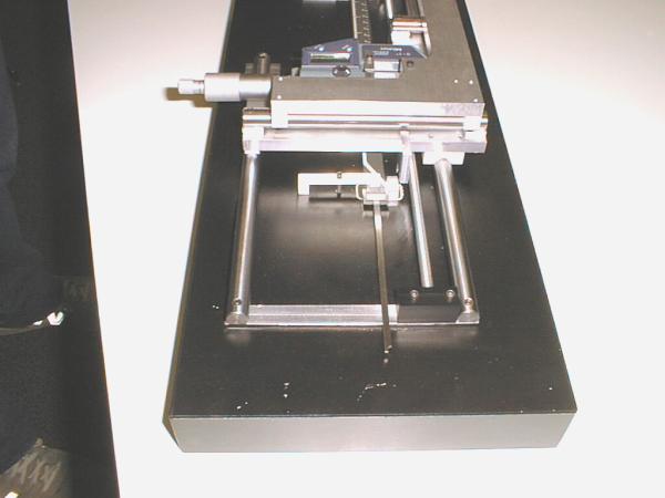
This short article shows some details of T. Lum's digital readout Caustic tester. Like all Caustic tester designs, this one can also be used for many of the other common ATM mirror testing methods. Built to a high degree of accuracy, it may be used to perform the Caustic, Foucault, Wire, and Ronchi tests.
This article outlines the results of construction of a Caustic Tester of high accuracy by a fellow ATM. Hopefully, these images will provide enough of an overview that such an instrument can be built by others. In an email to me, T. Lum writes:
"The fancy machining was more of my playing with my then "new" Bridgeport milling machine. It probably could be built with ordinary tools but with some more ingenuity.
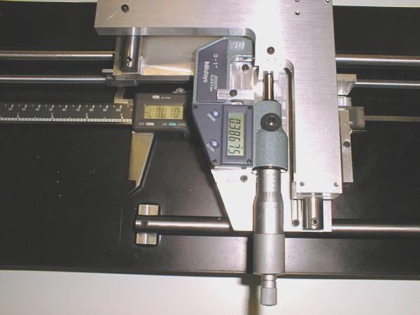
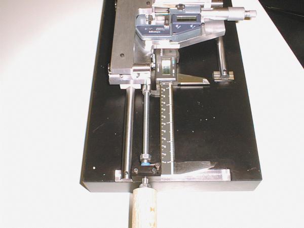
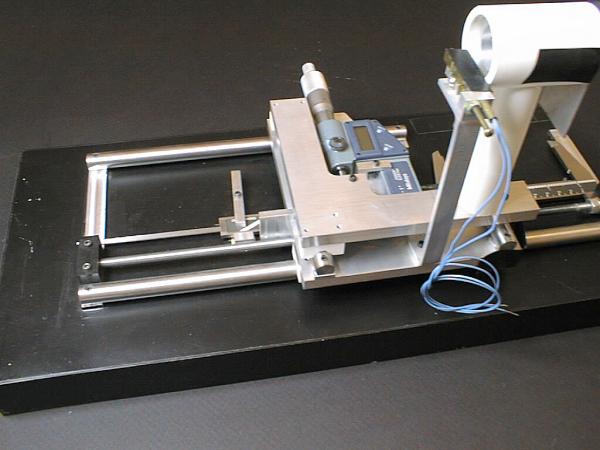
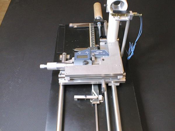
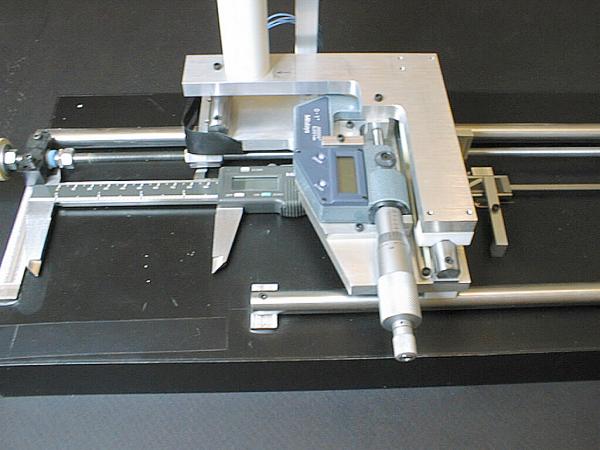
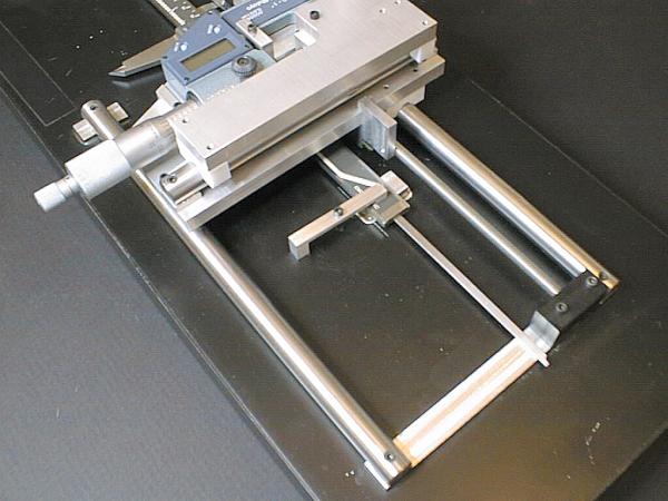
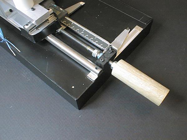
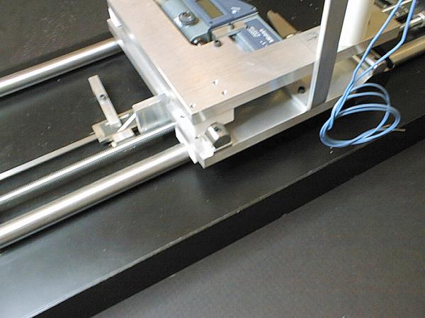
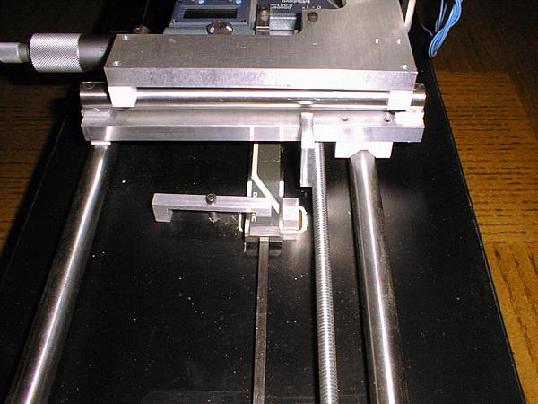
The rails are 1/2" drill rod stock from the local machine tool supplier. They are quite round, straight and smooth as purchased. The straightness and smoothness are the only important requirements. I did polish the rods with some fine wet-dry sandpaper and oil. The carriages slide on the drill rod on inverted Teflon "V blocks". I found that there was a maximum weight before the sliding had stiction. Just experiment. A rubber band is the return spring on the transverse carriage.
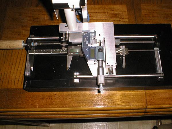
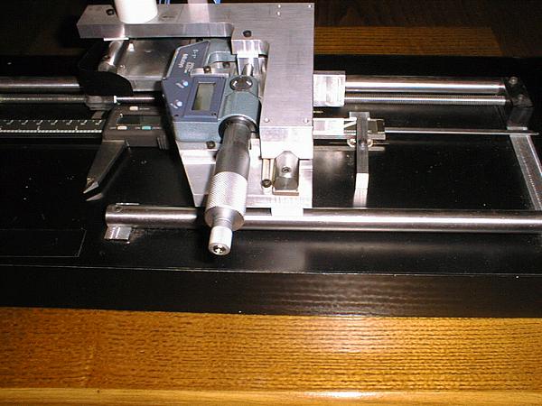
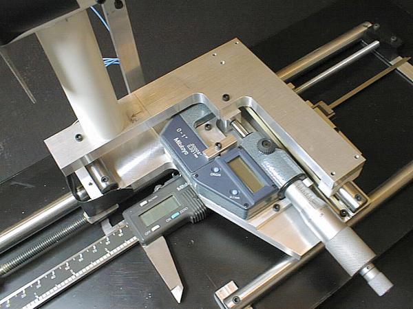
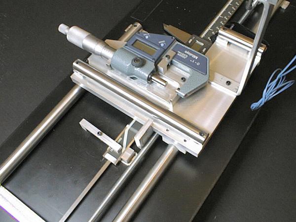
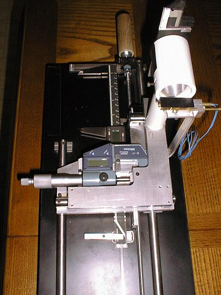
The transverse digital micrometer is a Mitutoyo reading to 50 micro-inches (1/2 a tenth", i.e. 0.00005"). The 3 volume ATM book article by Schroder recommended reading to 0.0001". I chose a digital micrometer mainly because my eyes aren't as good as they once were :) especially in dim light. Analog vernier micrometers of the same accuracy are significantly cheaper but obviously more difficult to read. The longitudinal micrometer is a digital caliper type I had bought for my machining measurements. The digital calipers have many convenience features like being able to make relative measurements by simply re-zeroing and the afore mentioned ease in reading in dim light. Both micrometers are held (gently) by clamps so they can be removed. The longitudinal caliper is my prime measuring tool when I'm machining so I couldn't afford (literally) to dedicate it to my caustic tester. The transverse carriage has a small ball bearing (individual balls can be bought at good bicycle shops) to bear against the micrometer spindle face to minimize (hopefully eliminate) any periodic error. Make sure that you provide kinematic restraints for the micrometers so that they can be removed and replaced without re-calibrating.
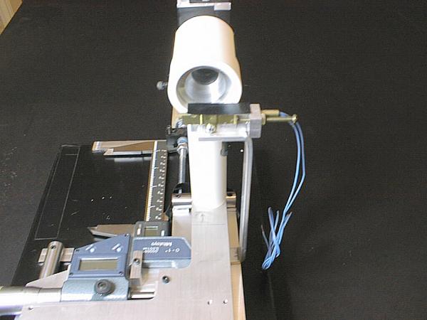
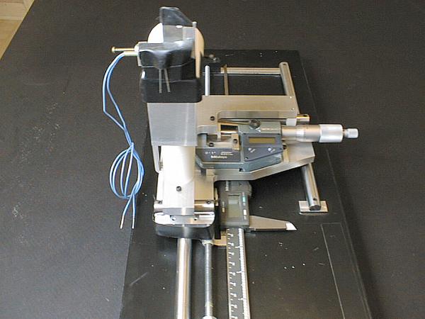
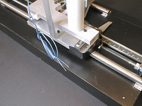
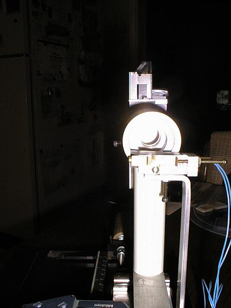
I made a holder for a 28-mm eyepiece I have behind the testing wire. See Schroder's article about the method. I'd make a improvement over what I did by providing more travel for the eyepiece to give yourself more flexibility in observing the diffraction image as described in Schroder's article. I can describe it in more detail if you need. The wire I used is a piece of 0.001" wire used for "wire-bonding" semiconductor die to the package. I got it when I worked for a major semiconductor manufacturer several years ago. I'm not sure where to get it if you don't have a friend in the semiconductor business. You may be able to find a fine wire in some small stranded wire.
Eventually, I'll write an article about my tester and explain why I made some of my decisions (assuming I can remember) and other particulars. Write if you need more info. -- T. Lum"
The above article is Copyright © 2001 T. Lum. It is reproduced here with permission. I have lost contact with T but can attempt to forward any emails to the last known private address if any readers have questions.
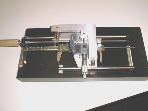
Additional Views of the Tester