An Ultra-Violet Exposure Frame
Make Your Own Printed Circuit Boards
John D. UptonJuly 15, 1998
You can build this exposure frame for making printed circuit boards. You will soon discover that it has quite a few other uses also. Install regular fluorescent bulbs and use it as a small light table for searching out pits on your optics or use it for sorting or stacking photographic slides or negatives.
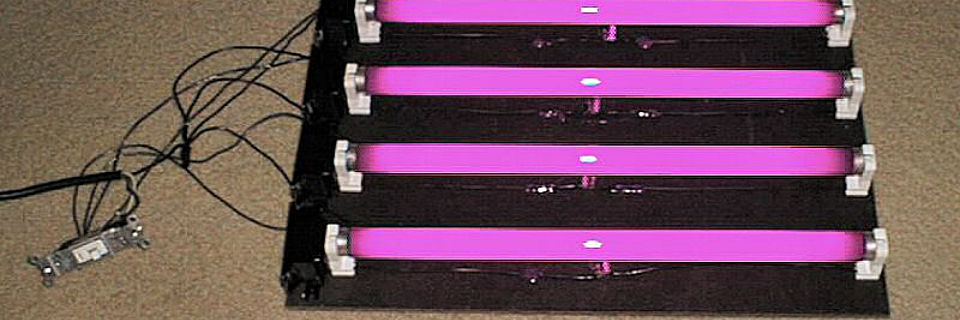
ATM's sometimes find the need to make their own PCBs (printed circuit boards) in order to complete a portion of their current project. Shown here is an Ultraviolet Light Exposure Box for exposing sensitized circuit boards. Parts for this project may be obtained from your local hardware or home improvement outlet. I used four 18 inch GE black light fluorescent bulbs in my design. You will also need four pairs of 15 watt fluorescent bulb sockets, four 15 watt ballast transformers (inductors), and four 22.5 watt fluorescent bulb starters (capacitor and thermal switch combination.) A full parts list appears at the end of this article.
I have also found this device doubles as a handy light table for many other uses. By replacing the UV bulbs with normal fluorescent bulbs, it can be used as a small general purpose light table for many of the other tasks often faced by ATM's.
The method of making circuit boards at home involves using a copper-clad fiberglass or phenolic board which has been coated with a photo-resist sensitive to UV light. The circuit pattern you wish to imprint on the board is then placed between the sensitized board and a source of UV radiation. After this exposure, the image of the circuit pattern on the board is then "developed" which removes the extra resist from areas where you want to remove the copper. The board is then etched in an etchant solution to remove this unwanted copper leaving the pattern of circuit traces represented in the design.
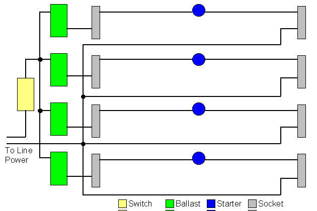
The bulb sockets, ballast, and starter are wired as shown in the wiring diagram. Each bulb's circuit is wired in parallel with the others. You may choose to use more or fewer bulbs in your design. I used four because it seemed to give very even illumination of the exposure surface and fit the maximum dimensions of any circuit card I am ever likely to make myself.
The base of the box with UV fluorescent tubes is assembled and wired first. Each bulb requires a socket set, ballast, and starter. The bulb sockets and ballasts are screwed to the masonite base board using two short sheet metal screws each. In order to make the design more compact, the starter components were removed from their metal cans and directly soldered into the wiring for the bulb sockets. The starters and wiring were then secured to the masonite base board using a few dabs of "hot glue" to keep everything from rattling around.
The base is next assembled into the plywood enclosure. The switch and power cord are installed through openings in the end of the box. The dimensions of the plywood box may be modified to suit your own requirements. Be sure to leave enough room between the UV bulbs and the diffusing screen to ensure adequately even illumination. I allowed about three and one half inches between the bulbs and the diffuser and spaced the bulbs about three inches apart. This proved to be a good compromise in my unit. The exposure times with this unit run from about 10 to 16 minutes. The actual time depends not only on the distance from the bulbs to the exposure surface, but also on the thickness and make-up of the glass or Plexiglas exposure surface. The different types of materials pass UV light in differing amounts.
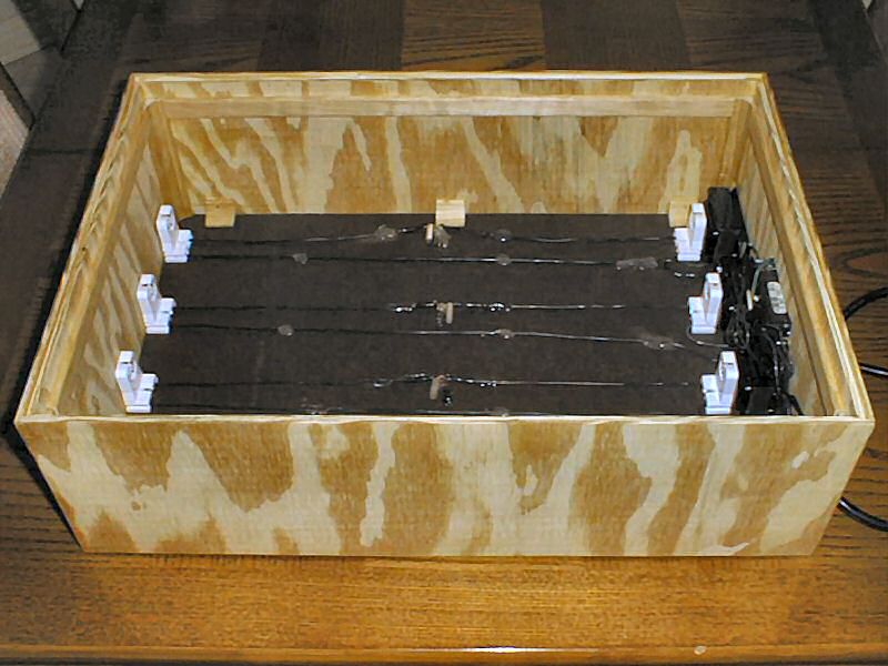
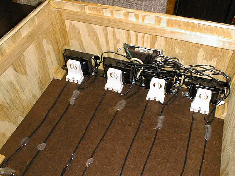
This photo shows the front end of the box and illustrates the mounting of the fluorescent tube sockets, ballast transformers, and power switch with wiring. It also shows how the wires along the bottom of the box are held in place with small areas of "hot glue." Note the narrow shelf inside the top edge of box used to hold diffusing screen and glass exposure surface in place. This shelf is made up of one quarter by three quarters inch cabinet molding glued around the inside of the enclosure. The diffuser frame rests on this shelf and the glass exposure frame rests on top the diffuser. I also installed short sections of three quarter inch cove molding into the corners of the box to add strength to the assembly. All joints in the plywood enclosure were glued and I found no need for brads or screws to hold everything together. The bottom is screwed to the enclosure in case I ever need to disassemble that part of the unit.
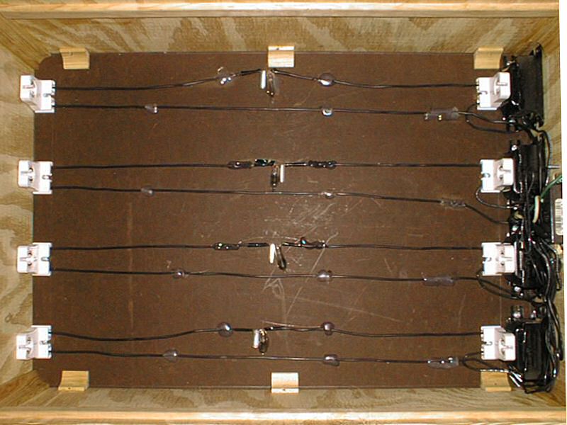
The masonite base board of the box holds all the electrical parts. The sockets and ballasts are screwed to the base and the wiring and starter components are held lightly in place with spots of hot glue at strategic locations. All these components are hidden by the poster board liner when the box is finally assembled for use.
This photo shows the inside of box after installation of the reflective liner. The liner is made of poster board with aluminum foil glued to the top side. The foil is cut back in areas near the electrical connections for the fluorescent tubes to prevent shorts and electrical hazards. The shape of the liner was laid out by carefully measuring the inside dimensions of the box and part locations, then transferred to the poster. The sides were laid out at the same time and a small amount allowance was made for overlap in the corners. The aluminum foil was then glued to the poster board using "white school glue." The board was next bent into the proper shape and fit into the box. There was no need for anything to hold it in place as the upper edges of the liner tend to spring outward and are captured under the shelf which holds the diffuser and exposure glass.
I should note that I originally intended to just use the white poster board to help diffuse the light throughout the box. I overlooked the fact that most white paper products actually absorb the UV light and re-radiate in the longer portions of the spectrum - they fluoresce quite well. This meant that the amount of UV available to expose the circuit board was reduced. The aluminum foil works quite well to help spread the light around the inside of the box and doesn't significantly change the wavelength makeup of the spectrum.
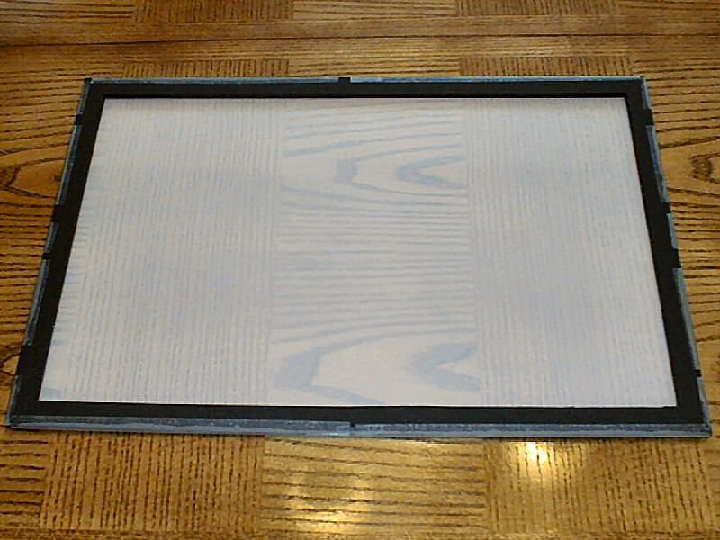
This photo shows the diffusing screen. It is made from a piece of matte drafting velum taped to a foam core poster board frame. The foam core poster board is about 0.25" thick. The side with the velum is placed on the shelf in the exposure box and the glass top is placed on top of it. This provides for a 0.25" gap between the diffuser and the glass giving good, even illumination.
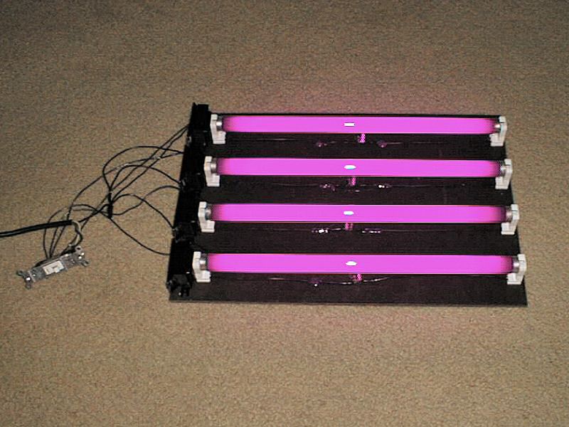
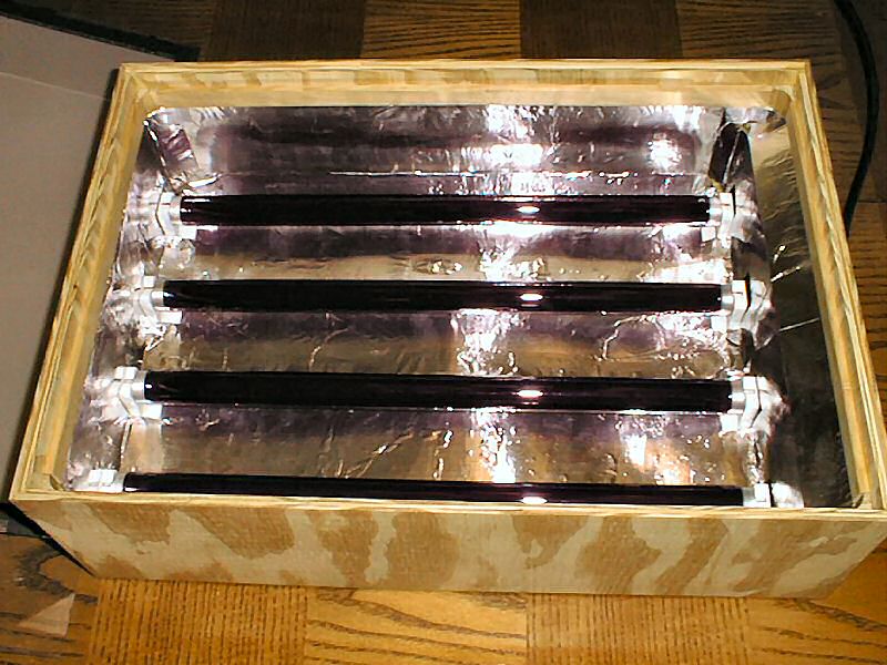
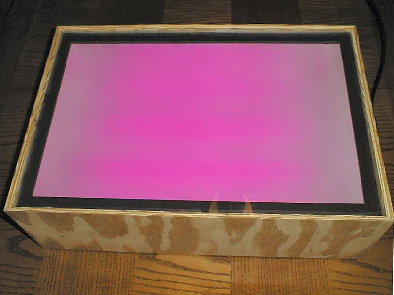
Here the unit is assembled (minus the lid) and turned on. The color is actually a very deep violet-blue but is not recorded well by the camera.
UV Light Frame Parts List
Part Description
Quantity
Part Number Suggestion
15 watt black light fluorescent bulb
4
GE F15T8/BLB or equivalent.
Flat-bottomed "medium" fluorescent bulb socket.
4 pairs
15 watt fluorescent ballast.
4
Valmont Electric 120PH-120 or equivalent.
15 to 22.5 watt fluorescent starter.
4
Surelite Products FS-25 or equivalent.
18 to 20 gauge 125 volt stranded hook-up wire.
200"
Cut to length as required.
120 volt wall mount light switch with cover plate.
1
Optional - spring driven wall mount 30 minute timer switch (Intermatic FD30MWC or equivalent.)
120 volt power cord.
1
Masonite or Plywood Base
14" x 20"
Plywood Lid (3/8" or 1/4")
14" x 20"
Plywood Sides (3/8" or 1/4")
2 - 6" x 20"
Plywood Ends (3/8" or 1/4")
2 - 6" x 14"
3/4" cabinet cove molding.
4 - 5"
Used to strengthen the enclosure.
3/4" cabinet cove molding.
4 - 1"
Used to strengthen the enclosure.
3/4" x 1/4" cabinet molding
2 - 20"
This forms the shelf for the diffuser and the exposure glass.
3/4" x 1/4" cabinet molding
2 - 14"
This forms the shelf for the diffuser and the exposure glass.
15 mil thick poster board
26" x 32"
Household aluminum foil
26" x 32"
Drafting velum
14" x 20"
Matte on one or both sides.
Foam-Core Poster Board (1/4")
2 - 14" x 20"
Only one 14" x 20" is required if the diffuser frame is made from 3/4" wide glued strips.
Glass or Acrylic Plastic
14" x 20"
Cabinet Hinges (Light-Duty)
2
1/8" long sheet metal or wood screws.
24
Solder and electrical tape or wire nuts for wiring connections.
As required
Glue or tape for securing loose parts and wiring.
As required
Woodworker's glue for box assembly.
As required
Cork or rubber "feet".
6
Self adhesive electrical project case feet.