Setting Up The Dall Null Test
Use OSLO-EDU To Calculate Your Dall Null Test Setup
John D. UptonOctober 15, 2000

Follow this tutorial to set up the Dall Null test for your mirror. Learn to use the power of the optical design program OSLO-EDU to calculate the correct setup parameters. You can also use OSLO-EDU to help you determine the quality of null to expect from this test as well as how much error latitude you have in assembling the tester.
After receiving several questions on my article describing the Dall Null Test, I decided that other amateurs might benefit from learning to do their own calculations for setting up this useful optical test. The traditional procedure for determining test parameters has been to consult the graphs accompanying the original Dall Null Test article published in the Amateur Telescope Making book series. (It may be found in Book III, page 149 of the 1952 edition or in Book I, page 315 of the 1996 Willman-Bell reprint.) In the original article by Horace Dall, the setup parameters are derived by reading values off a graph and doing a few very simple calculations.
With the availability of powerful optical design software for the personal computer these days, there is no reason to read your setup data from the published graphs. Instead, set up a test simulation and not only derive the test parameters, but also optimize it for your mirror and tester combination while gaining an in-depth understanding of the limitations of the test. In addition, when using an optical design program, you may set up the test for mirrors that are not paraboloidal. Thus you can use the Dall Null Test for all your non-spherical optics.
I have used OSLO-EDU from Sinclair Optics to simulate the Dall Null Test. The following procedure may be used both to help you determine the Dall Null Test parameters for your mirror and as a tutorial to learn more about how you can use OSLO-EDU to answer some of these common optical questions.
The procedure for simulating the Dall Null Test in OSLO-EDU can be quickly summarized as including the following steps.
- Start OSLO-EDU.
- Create an optical design with a plano-convex lens and a paraboloidal mirror.
- Place the pinhole light source near the lens.
- Optimize the setup to minimize spherical aberration.
- Adjust spacings to work with your tester.
- Do final optimization of the spacings.
- Investigate the tolerances for your test setup.
- Read out the values for your specific setup.
In describing the actions to take, I will state the menu items to use. Most of the things you will be doing will have toolbar buttons that can be used instead. It is often easier just to use those buttons. If you are already somewhat familiar with using OSLO-EDU, use the toolbar to do perform the steps in the tutorial.
Before getting into the specifics of the tutorial, I must mention that this tutorial assumes you are using Version 6.0 or later of OSLO-EDU. Sinclair Optics has recently updated OSLO to Version 6.0. The newer version features a much improved user interface. The problem that arises is that Version 6.0 completely changed the menu and window structure for most commands. The changes were so drastic that a second version of this tutorial had to be written. If you are using OSLO-EDU version 5.4 or earlier, please go to the copy of this tutorial which is specific to OSLO-EDU v5.4 now -- dall-setup.html.
Starting OSLO-EDU
Start OSLO-EDU running on your computer. If you are not familiar with OSLO-EDU, take a while and just play around with it. The tutorials that come with the program can explain a lot about how to use it in several different design methodologies.
Remember that OSLO-EDU data entry follows a simple "spreadsheet" format. If you draw out a simple layout diagram of your design, entry into OSLO-EDU will be very straightforward. Each surface traversed by a light ray is entered on a separate line in the spreadsheet. Each surface will include data on the curvature of the surface, the thickness (distance to the next surface,) the aperture radius (size) of the surface, the material (Glass) the ray is entering, and any special data pertaining to the surface such as its shape. Thicknesses are positive if the ray is traveling left to right and negative if traveling right to left. Radius of curvature values are positive if the ROC point is to the right of the surface and negative if it is to the left of the surface. Keeping these simple rules in mind will allow you to enter many different designs quickly and easily.
Entering Your Design
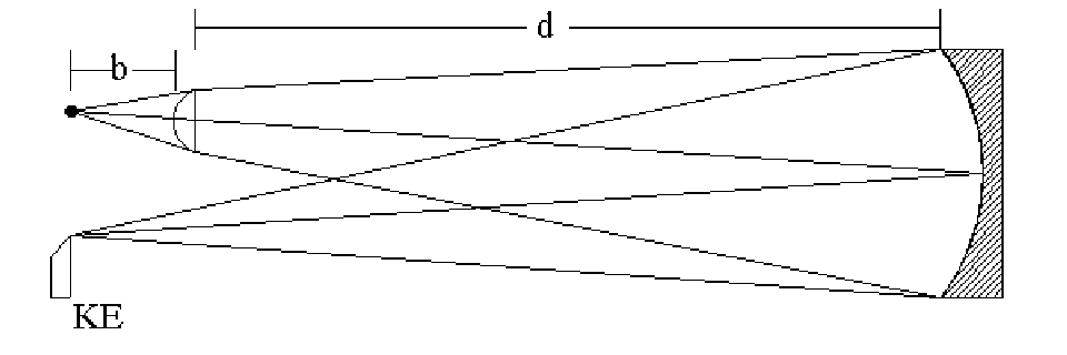
Now we will enter the Dall Null test design. The example here will assume we are going to be testing an 8" F/6.0 mirror with a 5.0" focal length lens which is 0.150" thick at its center. The lens is 1.0" in diameter. We will use the lens with the convex side facing the pinhole and the flat side towards the mirror as recommended by Dall.
First, open a new lens file by selecting File|New Lens... from the menus. Type a descriptive file name in the New file name: field. This will be the name of the saved design file. I will use "Dall_Null_8_F6" for my file name. For File type:, select Custom lens. Enter a 3 in the Number of surfaces: field. (The lens has two surfaces and the mirror is the third.) Now close the Command: File new entry box by selecting the OK button. The Surface Data spreadsheet will open. You may leave it open at this time while we do another short setup operation. Open the General conditions box by selecting the Gen button on the spreadsheet. Change the Units: entry to inches or your own measurement units of choice. You may also wish to enter your name in the Designer: entry field. Close the box and accept the changes by clicking the check mark near the upper left corner.
Next, we will enter our design data into the surface data spreadsheet. Click the mouse in the Lens: No name field and then enter a name for the design. (This is not the file name again. It is just a short description of what the design is.) I will use "Dall Null 8.0" F/6.0" as a design name. In the Ent beam radius field, enter half the estimated diameter of your nulling lens. You can enter mathematical expressions if you like. For our 1.0" lens, we can enter 1.0/2 and then press the Enter key.
Now, let's enter the Dall Null lens data. On the line in the spreadsheet labeled AST (for aperture stop,) click on the button in the Glass column. Select Catalog|Schott. In the glass listing box, select BK7 and then close the box accepting the change by clicking on the upper left check mark. Enter the center thickness of the lens (0.150" in this example) into the Thickness column of this same line (AST.) To see the focal length of the lens when we enter its radius of curvature, we want to temporarily turn on an automatic solve function for the lens. To do this, click on the button in the Thickness column of the spreadsheet line labeled 2. (This the the second surface intersected by incoming light -- the flat side of the lens.) In the pop-up, select Solves|Axial ray height... and then enter 0. (This asks OSLO-EDU to find the point at which the ray crosses the optical axis after leaving the lens.) You may ignore the result for now.
To enter the rest of the lens data, we need to find the radius of curvature of the first surface of the lens knowing its focal length. To do this we need the index of refraction of the lens. Since we assumed the lens to be made of BK7, we can find the index by using the Refractive index Data... menu item (labeled "Rin") in the OSLO Text Window. The information will be printed into the OSLO-EDU Text window. In the Text Window, click the mouse on the number at the intersection of the BK7 line and RN1 column. Note that you will get message on the command line below the command entry box of the spreadsheet that says something like a5=1.5168001097399. (In your case the a5 portion may be something else. You need to remember that letter-number combination, whatever it is for this run. It is the address of the index of refraction in the hidden spreadsheet buffer area of OSLO-EDU. We can use the address as a parameter now instead of retyping the complete number.)
Now we can enter the radius of curvature for the lens. Click in the Radius column of the AST line. Enter the formula (a5-1)*(5.0+(th[1]/a5)) using the letter-number combination you found above rather than the a5 I used. The a5 is the index of refraction and the 5.0 is the specified focal length of our lens. This formula calculates the radius of curvature by taking the index of refraction of the lens minus 1 and multiplying it by the focal length plus the optical thickness of the lens. (The th[1] in the formula is OSLO-EDU notation for the thickness of surface 1. If everything worked correctly, the Thickness column of surface (spreadsheet line labeled) 2 should have now solved the correct focal length of the lens. For our example it now shows 5.00000 inches.
Our final data entry task is to enter the mirror parameters. To do this, enter the radius of curvature (as a negative number) for the mirror in the Radius column of surface 3. Remember that you can use formulas, so I can enter -8*6*2 for my 8" F/6.0 mirror. To make this a reflective mirror surface, click on the button in the Glass column and select Reflect (Hatch). Finally, to make this a paraboloidal mirror, click the Special button for surface 3 and select Polynomial Asphere|Conic/Tonic. In the Conic/tonic data box that opens, specify the Conic constant as -1.000 and close the box accepting the changes. Now click in the Thickness column for surface 2 and type -rd[3]-rd[1]-th[1] to place the lens at approximately the correct position for the null test. Finally, turn on the Solve|Axial Ray Height... for the Thickness of surface 3 and enter a solve value of 0. This will place the image surface at the paraxial focal point for our test set-up.
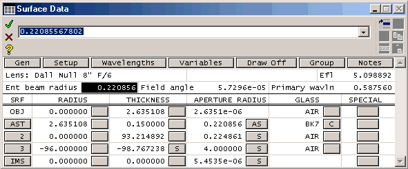
The last step before optimizing is to move the light source near the lens and adjust the aperture so that light just covers the mirror. To do this, click in the Thickness column of the OBJ (object) line of the spreadsheet and enter rd[1] to set a starting point of having the pinhole at a distance from the lens equal to its radius of curvature. When we do this, notice that the Aperture Radius at the mirror is now over 9" for our 8.0" example mirror. That is much more than required. We need to get that value down to near 4.0" in order to just cover the mirror diameter with the light exiting the lens. One way to do this is to click in the Object Numeric Aperture field near the top of the spreadsheet to get the current value into the command entry box. Now click in the command entry box near the end of the number field there. We can now edit the number. Let's scale it by an amount proportional to how far off we are by typing *4.0/ap[3] after the original number and then pressing Enter. We can repeat this operation a few times until the Aperture Radius at the mirror is near 4.0. At this point in the tutorial, your lens data spreadsheet should be similar to the one below.
Optimize For Minimum Spherical Aberration

We are now finally ready to begin optimization of the design. We want to minimize the overall spherical aberration of the design to give us the best case null setup. To start the optimization, select the Optimize|Generate error function...|Aberration operands... menu item. Now, select the Optimize|Operands... menu item. Note that Operand OCM20 represents the total spherical aberration. This is the parameter we want to use. This will optimize the total spherical aberration of the test setup. To remove the other operands, click on the button on line 1 then hold down the shift key and click on line 19. A box will be drawn around entries 1 through 19. Now click on the cut icon (scissors) in the upper right corner. Now click on line 2 and cut that line. You should be left with only the OCM20 operand line. Close the Operands data editor box. Now we must set which parameter to vary during the optimization. We want to optimize the source (pinhole) to lens distance which is the object thickness. To do this, click on the button in the Thickness column of the OBJ line and select Variable from the pop-up list. This allows the program to optimize the spherical aberration by changing the pinhole to lens distance.
To begin the automatic optimization, select the Ite menu item (labeled Ite) on the text window. This will run the optimization routine for up to 10 iterations and then stop. The status message in the text window will show how many iterations were actually run. If the number reported is 10, the optimization may not have completed homing in on the best setup and you should repeat the iterate command.
The lens data spreadsheet will be updated with the new setup values. You should check to see that the Aperture Radius value listed for the mirror (surface 3) is still large enough to just cover the mirror. If it is too large or too small, adjust the Object numeric aperture field value as we did before to bring it back close to the mirror radius size. If you did need to adjust the Object numerical aperture, you should again repeat the optimization.
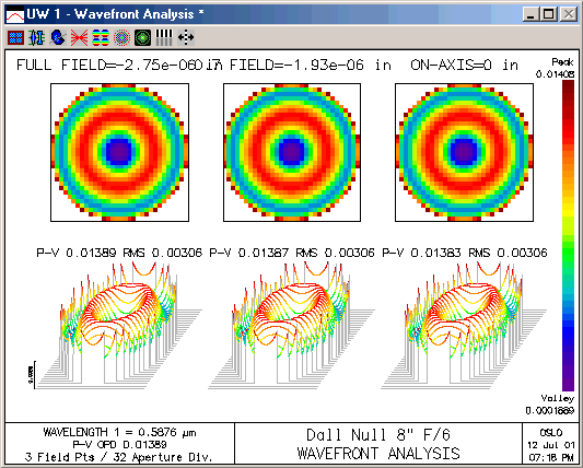
You can also now find out how good a null has been obtained for this set up. To do so, select the Autofocus|RMS monochromatic menu item (labeled Auf) on the Text Window to refocus for minimum spot size and then select the Plot|Report Graphics Wavefront Analysis... menu item from the graphics window. You will see a graphic representation of the wavefront in the graphics window. In the last column of graphs (labeled On-Axis,) you will find the P-V and RMS wavefront optical path differences listed. Typical values for this example analysis are P-V = 0.014 and RMS = 0.003 waves. This is the overall quality of the null for your mirror and lens combination measured in wavelengths at the evaluation wavefront.
Adjust The Test Setup and Optimize The New Settings
After performing these steps, you may find that your tester setup will be inconvenient to use. For example, my set up finished up with the lens 2.753" from the pinhole and the lens 93.2" from the mirror. Adding in the thickness of the lens, I find that the pinhole to mirror distance is 96.1" while the return beam focuses at 92.9" from the mirror. Because of this, I cannot get my eye near the converging beam because the tester light source and lens assembly is in my way. The beam is focusing about 3.2" in front of the tester. Ideally, I would like the converging beam to come back to a focus about 1" behind the pinhole for my tester.
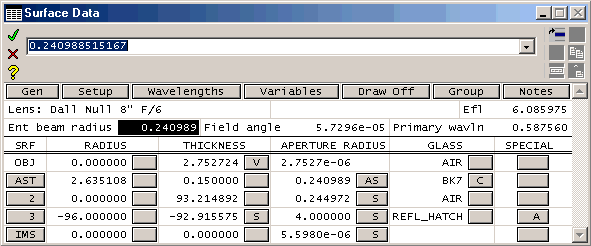
To solve this setup convenience problem, I will play with using a different lens to mirror distance. I will move the tester forward by half of the 3.2" distance and then about another 0.5" to give me closer to 1" extra clearance. To try this out, I change the Thickness of surface 2 (the lens to mirror spacing) to 93.2-1.6-0.5 = 91.1". After making the change, I again adjust the Object numerical aperture to make sure the beam will fully illuminate the mirror, and rerun the optimization. After making these changes, I find that my final distances are 2.717+0.15+91.1 = 93.97" from pinhole to mirror and 95.0" from mirror to focal point. Now the beam is converging about 1" behind my tester. That is just where I wanted it to be. My final optimized setup data looks like this:
Check The Test Quality And Tolerances
Now that we have the setup optimized to minimize spherical aberration and match our tester's design, let's see just how good a null will be produced for this mirror. Use the Plot|Report Graphics Wavefront Analysis... graphics window menu command to again display the wavefront analysis in the graphics window. Below, we see that the test setup for my 8" F/6.0 mirror yields a null to better than 1/50 wave peak-to-valley at the evaluation wavefront.
We now know that we can get a good null, but how much leeway do we have? Do we have to duplicate the setup we just found to five decimal places to use the test? To find out, let's use the power of OSLO-EDU to answer our questions.
Let's first see how much tolerance we have in placing the tester. If our positioning of the tester was off by 1" toward or away from the mirror, how would that affect the quality of our null? To see, just enter 90.1" for the thickness of surface 2 instead of 91.1. Refocus the setup and refresh the wavefront analysis window. (Be sure not to optimize the design. We only want to see what effects our 1" setup error has. For that, we only need to refocus the design.) The new wavefront analysis now shows that we still get better than a 1/15 wave P-V null for a 1" tester placement error. (In general, you would want to set a personal standard for how much the error to accept in the null. I am generally comfortable with as much as 1/8 wave (measured on the wavefront) nulling error.) Set thickness 2 back to 91.1, our optimum design value.
Next, let's see how critical the all important pinhole to lens value is. Let's assume we don't think we could measure that design element to closer than 0.010". Using a value of 2.727 instead of the 2.717 optimum value, we find after refocusing that the null has dropped to just a bit better than 1/25 wave. This is still quite good and gives us confidence that we can build an accurate tester. You should see that you can go through each of your design parameters and quickly see how much error margin you will have in setting up the test.
When tolerancing your setup, keep in mind that each of these set-up errors will be cumulative, so you want to strive for the best tester and setup possible. Being a little off in each parameter is okay so long as you understand what the total effect will be. In general, you should be able to easily see at least a 1/4 wave (on the wavefront) error in the nulling of a mirror, so you should keep your overall tolerances and nulling error margin below the threshold of visibility. With careful observation, you will probably be able to detect errors down to the order of 1/10 to 1/15 wave.
You should always be very sure that the Aperture Radius value for Surface 3 (the mirror) is just large enough to cover the actual mirror. The wavefront error analysis is affected by this value. If too small, like 2", the P-V wavefront error reported will be only the amount for that central 4" diameter of the 8" mirror. Thus, it will be overly optimistic. In the same way, if the Aperture Radius of surface 3 is too large, you will get the wavefront analysis for a larger mirror that will be too pessimistic for the mirror you are testing.
Reading out the Setup Values
Note that the working diameter of your null lens can be read from the setup data. For the example 8" mirror we are using, the lens will have to be at least 0.5" in diameter. (This is twice the maximum Aperture Radius of the lens.) Since the lens should be of good quality across this aperture, it is often best to chose a lens of about twice this total aperture so that just the center portion is used. My lens in this example was 1" in diameter, so it should work fine.
All that remains is to adjust the pinhole to lens distance on my tester to 2.717" and place the tester so that the lens to mirror distance is about 91". I am ready to begin figuring my mirror and verifying progress with the Dall Null test.
Conclusion
Hopefully, working through this example shows how easy it is to set up and optimize the Dall Null test. You should now be able to set up a similar simulation of the test using OSLO-EDU and the parameters from your own mirror and nulling lens. Even if you are building a telescope requiring a non-paraboloidal mirror like a Dall-Kirkham cassegrain, you can still make use of the Dall Null test to figure your primary. Just enter the proper design value for the Conic Constant of your mirror and proceed as we did above. Learn to use OSLO-EDU in situations like this, and a whole new range of testing possibilities will become available to you.
Acknowledgement
I would like to thank Ken Bertapelle for the excellent job he did in proof-reading and editing this article prior to publishing on this Web Site. Ken helped greatly by translating the command procedures to match the newer version of OSLO-EDU. In addition, Ken put together a checklist for following this tutorial. He has agreed to allow me to distribute his checklist from this site. Thanks, Ken.
- View/download Dall-Null-OLSO-Checklist.pdf

